 |
DATAKIT SDK
V2026.3
|


|
|
DATAKIT SDK
V2026.3
|
|
Before reading this How-to, you should be familiar with Dtk_MainDoc / Dtk_Component / Dtk_Node concepts. Here some links to these documentations:
Dtk_MainDoc / Dtk_Component - Dtk_Node -DATAKIT has introduced the Dtk_NodeConnector, a new way to connect entities in the MainDoc context.
Dtk_NodeConnector can be retrieved by the Dtk_Node::GetAssociatedEntities method.
The Dtk_NodeConnector aims to link a Dtk_Node to a Dtk_Node or a Dtk_Component and even some subentities into Nodes.
For that, the Dtk_NodeConnector provides this information - ordered by granularity-:
Here are some Dtk_NodeConnector sample values and the corresponding link nature:
| Component PathID | NodeID | SubEntity array - ID/type form - | Corresponding Link |
|---|---|---|---|
| - | - | - | The whole Local Component |
| - | 3 | - | In the Local Component, points to the whole Node 3 |
| - | 3 | 50/DTK_TYPE_LINE | In the Local Component, points to SubEntity 50 - of type DTK_TYPE_LINE - in the Node 3 |
| 1 - 4 - 3 - 10 ( - 9 ) | - | - | The whole Instance 10 ( with the Prototype 9 ) from the path 1 - 4 - 3 ( where 1 is the root ) |
| 8 | 10 | 99/DTK_TYPE_BODY | In the Prototype 8, points to the SubEntity 99 - of type DTK_TYPE_BODY - in the Node 10 |
The component PathID points to the corresponding Dtk_Component context.
For this, the path starts from Owning Component and goes through each component to the according context. It's a relative Component Path ID.
In some cases, it can start from the root Component - usually 1 -. The path ID is then an absolute Component path ID.
When you have an Instance ComponentID, it may be followed by the corresponding Prototype ComponentID.
To retrieve the Component Path ID, please use the Dtk_NodeConnector::GetAssociatedPathComponentID(Dtk_tab< Dtk_ID > &outAssociatedPathComponentID) const method.
You will obtain different results depending on the link nature:
Dtk_NodeConnector points to the Local Dtk_Component the PathID will be empty.Dtk_NodeConnector points to a prototype component - i.e. all instances of a part for example -, The PathID will contain only 1 ID - the prototype component ID -.Dtk_NodeConnector points to an instance component the PathID will contain several IDs meaning the relative or full path.
The NodeId points to an entity in a given Component context.
To retrieve the NodeId value, please call the Dtk_NodeConnector::GetNodeId() method.
All Nodes can be pointed.
The NodeID can be zero-valued if the connector points to the whole component.
If it's zero-valued, the Dtk_NodeConnector::GetSubEntitiesNb() method should return zero also because we can't provide SubEntities without a containing Dtk_Node.
When a Dtk_NodeConnector points to a piece of Dtk_Node - typically a face in a Dtk_Body -, the SubEntity array is filled.
To retrieve the SubEntity array please use the Dtk_NodeConnector::GetSubEntities(Dtk_tab< SubEntity > &outSubEntities) const or
Dtk_NodeConnector::GetSubEntities(Dtk_tab< Dtk_ID > &outEntitiesIDs, Dtk_tab< type_detk > &outEntitiesTypes) methods.
Each SubEntity provides an ID and a type corresponding to the pointed entity ID/Type. The SubEntity array can exist only if a NodeID is provided - no zero-valued -.
DATAKIT API provides a Dtk_MainDoc.
It's a convenient way to handle multiples files/parts or heterogeneous CAD systems.
However, we can't store huge assembly data into memory. So Dtk_Component information are not stored entirely.
To retrieve information of a specific Dtk_Component the integrator has to call the Dtk_API::ReadComponent method.
If you want to handle extra Dtk_Component entity connections - From Component A to Component B -, keep in mind that if you switch Dtk_Component context - by calling Dtk_API::EndComponent / Dtk_API::ReadComponent calls -, you will reread the pointed physical file and do a full reading. It's very time-consuming.
In the same way, successive calls to Dtk_Node::GetXXXXPtr - for example Dtk_Node::GetBodyPtr() - methods will reread the wanted geometry. It's not always what you may expect.
To avoid this, DATAKIT provides you with some tools to access to your entities only once.
Let's get the sample case explained by this picture:
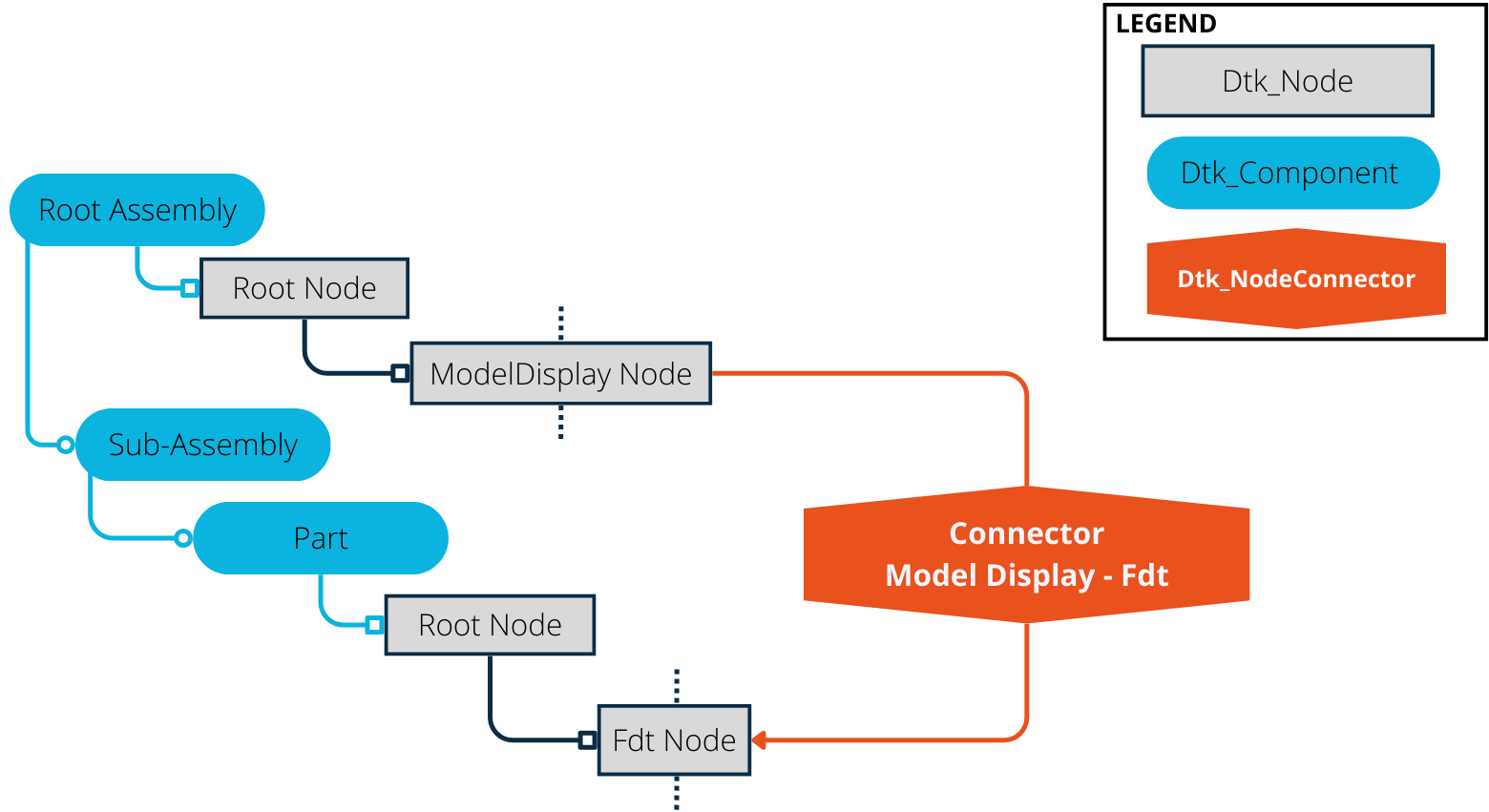
As illustrated, we have a 'Root Assembly' containing a 'Sub Assembly'.
This 'Sub Assembly' contains a 'Part' which has a PMI.
The 'Root Assembly' also contains a ModelDisplay which has a Dtk_NodeConnector pointing to the Part PMI.
Keep in mind that you can't reread the part component when you have the Dtk_NodeConnector in the Assembly context because it would increase dramatically the processing time.
So you should read the 'Part' Dtk_Component prior to read the 'Sub Assembly' one - and of course the 'Root Assembly' one -.
After the call To Dtk_API::ReadComponent( PartComponent ) you will be able to call the Dtk_Component::GetConnectorsPointingToThisComponent method.
It will provide you a list of all Dtk_NodeConnector pointing to the Part Component - including the ModelDisplay To PMI one -.
Once you have the Dtk_NodeConnector you can call the Dtk_API::ReadConnectedEntity method to retrieve directly the pointed EntityPtrs - 1 or several -.
You can alternatively use successively:
Dtk_NodeConnector::GetNodeId() with Dtk_Component::GetNodeByID() to retrieve the good Dtk_Node .Dtk_NodeConnector::GetSubEntities() and Dtk_Body::GetEntity() to retrieve the subentity - typically a face into the Dtk_Body -.Dtk_NodeConnector::GetAssociatedPathComponentID() will only be informative because you are already in the good Dtk_Component context.As an integrator, if you want to connect the ModelDisplay to the PMI you should tag in your context the provided entity to be referenced later.
Once your are in the 'Root Assembly' Dtk_Component and access to the ModelDisplay Dtk_Node , you can retrieve the connections starting from the node by calling the Dtk_Node::GetAssociatedEntities method.
It will provide you a Dtk_tab of Dtk_NodeConnector .
At this point you should ask in your database the entity previously read and related to the Dtk_NodeConnector data.
IMPORTANT: Don't compare the Dtk_NodeConnector directly because they can be different.
Compare only the data - Component PathID / NodeId / SubEntitieId -.
You should now be able to connect the ModelDisplay to the PMI in your database.
Dtk_NodeConnector can come with a reason ( see Dtk_NodeConnector::ReasonLinkEnum ) to help you determine their use case. You can retrieve this information by calling Dtk_NodeConnector::GetReasonLink.
Reasons listed in the "General Associations" category (Dtk_NodeConnector::ReasonCategoryEnum) will be detailed in this section.
Be aware that even if efforts are made to provide a unified representation of such information, some formats could be mapped with slight differences.
Those can be explained by a will to avoid over-interpreting limited data, caused either by format or reader limitations.
This case usually represents link from Dtk_Fdt to its associated geometry (Dtk_Face,Dtk_Edge or Dtk_Vertex).
In such cases, Dtk_NodeConnector::GetPointedEntityType() help you determine the kind of geometry is associated to the Dtk_Fdt.
This information is the same as the type you can find when browsing the subentities ( see Dtk_NodeConnector::SubEntity ).
The Dtk_Fdt usually linked to geometric elements are the Dtk_Dimension and the Dtk_GeometricalTolerance.
This case usually represents link from an entity to its associated feature (Dtk_feat).
The containing Dtk_Node type, or the use of Dtk_NodeConnector::GetPointingEntityType() allow you to identify who is pointing the Dtk_feat.
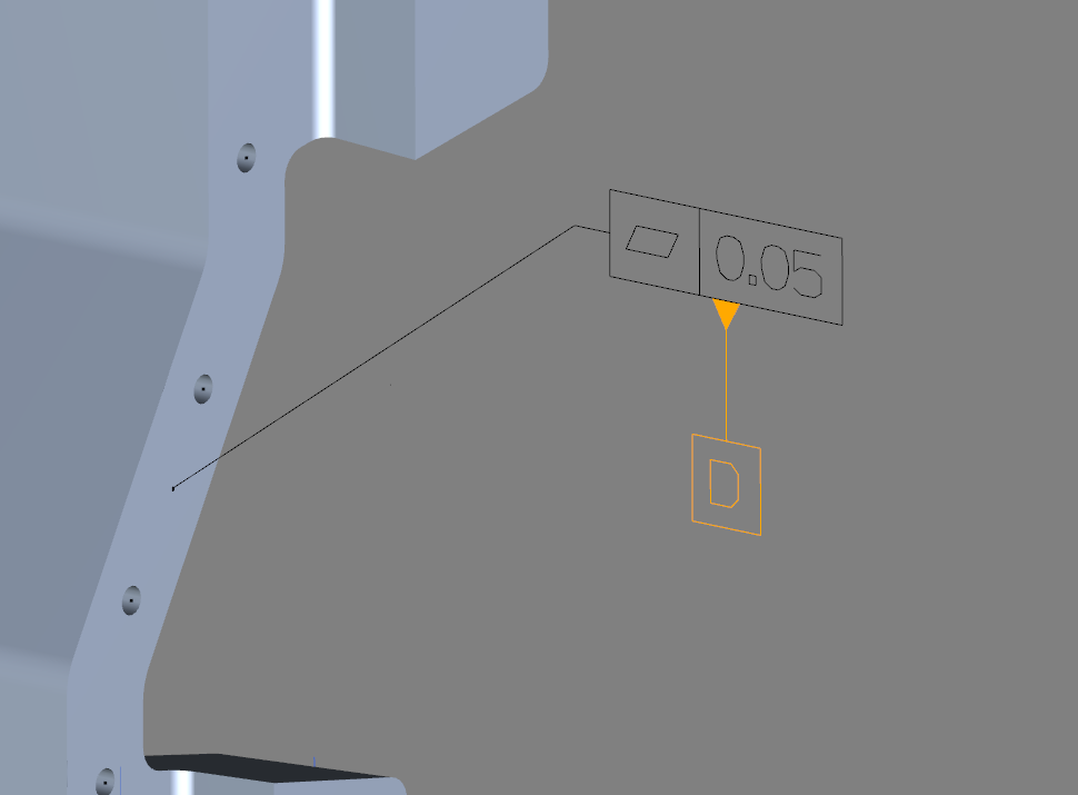
This case represents link from a PMI to another PMI (Dtk_Fdt).
This association can be used in cases of purely-graphical bound for example, as illustrated below.
This reason allows to cover general cases of Annotation association being a default behaviour of the software producing the CAD.
It can thus act as a link from PMI to its associated geometries being affected by default. (Catiav5)
In can also represent link between a hole feature and its note that was generated by default, because of standard hole definition. (ProE)
This reason allows to represent rather unusual cases of PMI having link to associated geometries of a specific kind (that is, different from the basic case of AssociatedGeometry).
Indeed, the geometry being highlighted in the software while selecting a PMI can be different than the actual associated geometry.
In such a case, we use this reason to make a difference.
This reason allows to cover general cases of an entity definition being based on another entity.
Here is an non-exhaustive list of examples :
Dtk_ModelDisplay to Dtk_ModelDisplay). Dtk_Camera being the same.Dtk_Fdt to Dtk_Face).This reason allows to represent rather unusual cases of a whole Dtk_Component who makes usage of the context of another Dtk_Component.
For example, Catiav5 PartARM concept is handled this way.
In such a case, the root node of the PartARM Dtk_Component will have a Dtk_NodeConnector to the Dtk_Component it uses as a context.
If the Dtk_NodeConnector reason is set to its default value, either the connection is defined as-is in the format, or its context makes it unambiguous.
A common case of Dtk_NodeConnector with Unknown reason, is a Dtk_ModelDisplay listing the Dtk_Fdt it contains / it is associated with.